A bistable multivibrator (flip-flop) is an electronic circuit that allows for manual generation of a square wave signal at the output.
The bistable flip-flop has 2 outputs. When one has a high state (logical “1”), the other has a low state (logical “0”), and vice versa. The name of the circuit comes from the two stable states (“ones”) that appear alternately during its operation.
Admittedly, generating a useful control signal by manually switching the inputs is rather impossible, but analysing the operation of this circuit helped me understand the principle of operation of the astable multivibrator described in a separate article.
I am constantly learning, so for experienced professionals, my descriptions may be overly simplified, and in some places even childish. I also reserve the right to make mistakes.
Conclusion: criticise, but don’t hate; read, but better not quote :)
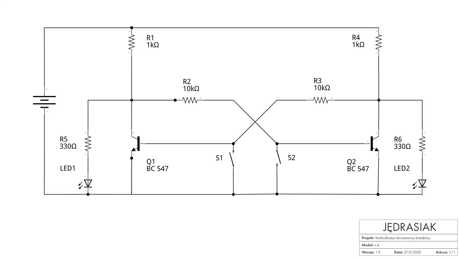
Bistable multivibrator – schematics

Bistable multivibrator – description
Circuit outputs
The outputs of the bistable multivibrator, where square wave signals are generated, are located at the collector-emitter (CE) junctions of transistors Q1 and Q2. To better visualise the effects of the circuit operation, I connected an LED to each of them.
LED1 conducts (lights up) when transistor Q1 is off, and Q2 is saturated. Correspondingly, LED2 conducts when transistor Q2 is off, and Q1 is saturated. At first glance, such cross-generation of signals may be confusing, but the explanation for this phenomenon is simple.
If we look at the schematic for a moment longer, we will notice that transistor Q1 and resistor R1 (and correspondingly Q2 and R4) together form a voltage divider. When a given transistor is off (not conducting), it behaves like a resistor with a very high resistance. In this case, the voltage across its junctions is determined by the following formula:
$$ Uout = Uin * \frac{Q1}{R1+Q1} $$
The voltage across the collector-emitter junctions of the transistor causes the connected LED to light up. Similarly – when the transistor does not conduct, it behaves like a resistor with low resistance, with only minimal voltage across its junctions – the diode does not light up then.
Step-by-step operation
Under ideal conditions (if all components had the same parameters), such a constructed bistable flip-flop would not be able to operate. At any given moment, both transistors would have to simultaneously conduct and not conduct, which is rather impossible. However, individual elements of the circuit differ slightly from each other, which allows one transistor to start conducting faster than the other after powering up the circuit.
In the model I built, transistor Q2 turned out to be faster, so we will start with it.
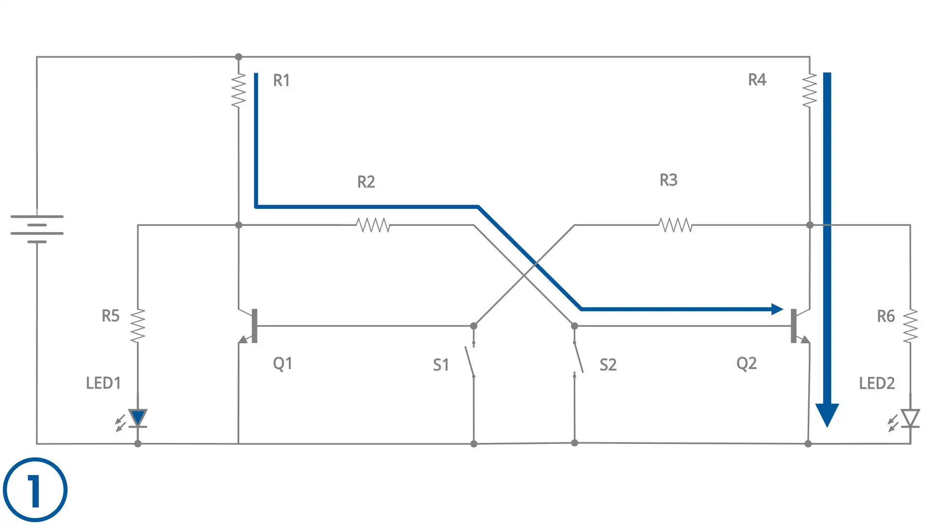
Phase 1
- Both buttons open,
- Current flows to the base of transistor Q2 through R1 and R2 – Q2 conducts,
- Q1 is off – LED1 lights up.
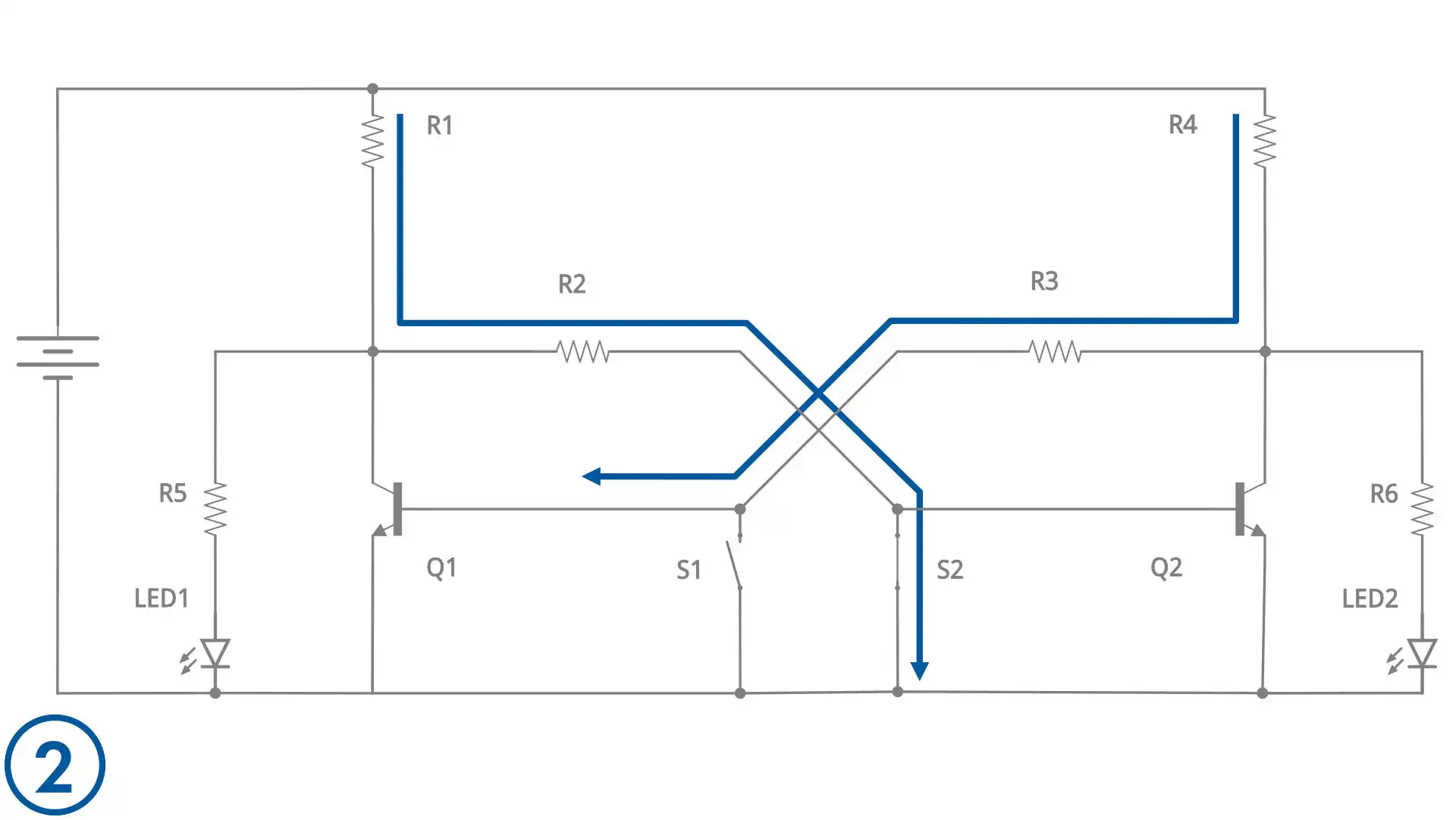
Phase 2
- Button S2 closed – current “shortcuts” and does not reach the base of Q2,
- Q2 is off – current starts flowing to the base of Q1 through R4 and R3.
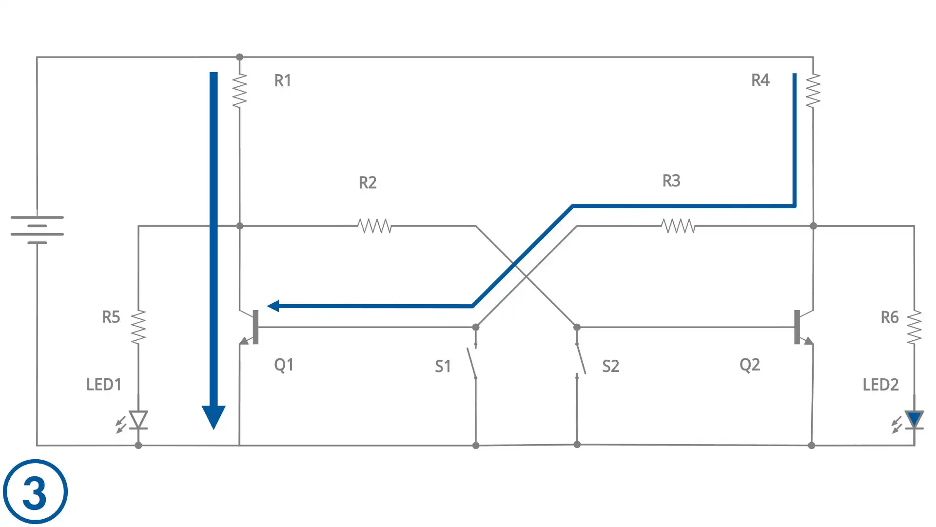
Phase 3
- Both buttons open,
- Current flows to the base of Q1 through R4 and R3 – Q1 conducts,
- Q2 is off – LED2 lights up.
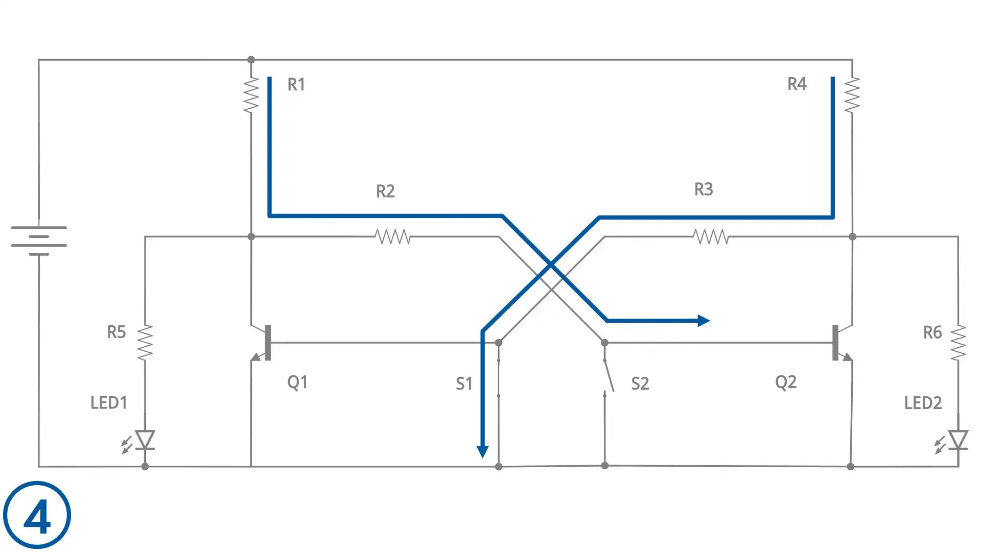
Phase 4
- Button S1 closed – current “shortcuts” and does not reach the base of Q1,
- Q1 is off – current starts flowing to the base of Q2 through R1 and R2.
The next phase is a repetition of phase 1, so this is where the operating cycle of the circuit ends (which, of course, can be repeated any number of times).